Installation
Calibration
Since I wanted to know the exact amount of fuel remaining on the boat, I calibrated the tanks. I measured the angle of the mounts for each tank and blocked the tanks on the dock to the same angle. I installed all fittings and temporarily wired the level senders to the gauge. Using a measured gallon container I added a gallon at a time, recording the level shown on the gauge and the inches of fuel shown on the sounding tape. I was also able to record the set point of the high level alarm for each tank.
The WEMA tank sender is a voltage divider made from reed switches and resistors. The sender moves the gauge in discrete increments corresponding to the magnet in the float activating the next successive reed switch. For each marked increment on the gauge face I recorded the minimum fuel required to reach that level.
Parts and Consumables
Some of the miscellaneous parts and supplies I bought to install the tanks:
- The sounding tape is a stainless steel ruler cut lengthwise to fit into the 3/4" NPT opening.
- All stainless steel pipe fittings were purchased from McMaster-Carr.
- Brass 8 port manifold from McMaster-Carr.
- Nitrile rubber from McMaster-Carr
- Brass visual flow indicator
- Vane Puppy fuel transfer pump
- 3/8" fuel line
- BandIt Banding tool and .030" banding material for tank holdowns
- Stainless channel to manufacture tank hold down brackets - OnlineMetals
- Locktite 545 Hydraulic sealant for thread compound. With over 100 sealed fittings in the system I had no leaks.
Because of limited space above the tank I found myself buying more expensive high-pressure fittings because they have a lower profile. For a couple of the vent lines I needed even lower-profile fittings, I discovered my welder was able to make fittings from stainless pipe nipples for the cost of a case of beer on a Friday
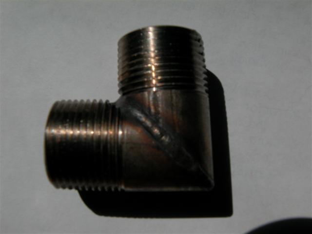
Low profile vent fitting custom made by Ballard Sheetmetal.
Tank Mounts
The tanks are mounted on polypropylene bar stock with 1/8" nitrile rubber strips both on top and underneath the plastic bar stock. Gluing the rubber to the polypropylene is marginal but keeps the rubber in place during installation. The gap between the bilge and tank bottoms varied from 3/8" for the forward-most tank to 2-1/4" for the day tank.
Another issue is the floor. The floor was supported by the old tank and flexed too much without additional support. Since I had allowed for 1/4" nitrile rubber between tanks, I determined I had room to increase this to 1/2" without encountering additional obstructions. I placed 1/2" teak boards mounted on polypropylene between each tank to support the floor. I will add additional floor supports when I remove the forced air heater duct.
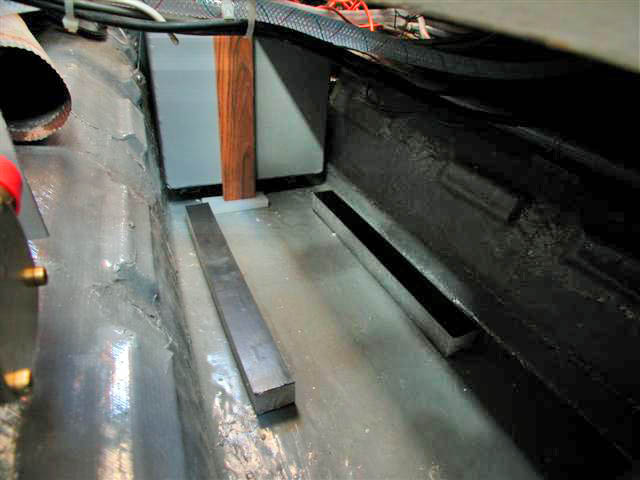
Tanks sit on polypropylene plastic, note the stainless steel strapping holding down the day tank
The tanks are the maximum height allowed by the bilge height at the table pedestal. Since the tanks slide into position in the bilge as far away as 6', the mounts can not be permanently attached. For tanks 4 and 5 the tank mounts were placed prior to tank installation and are continuous rails under the tank. Tanks 1-3 use four short plastic bars each, one in each corner. The bars are positioned as each tank is maneuvered into position. The tanks and mounts are held in place by the downward force of the tightened stainless steel strapping.
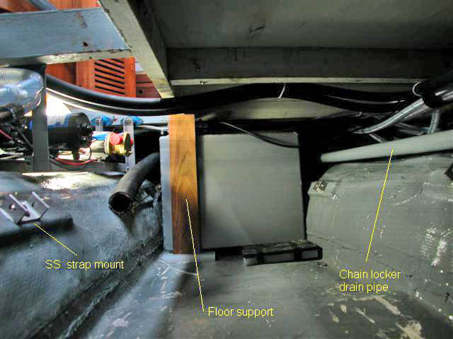
Adding the next tank
As each tank was installed pipe fittings were added after the tanks were in place. In the photo above note the new water lines running through hangers attached to the underside of the floor. These water lines can be replaced by attaching a new hose to the old one and pulling the new hose through the hangers.
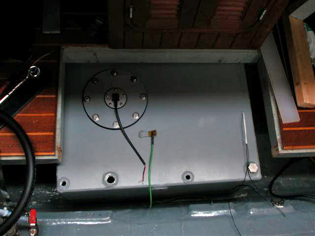
Next one drops in, slides back
Tank number three going in. This one spanned a 'shelf' in the top of the bilge and required careful shimming to make it sit level. This tank could have been an inch shorter.
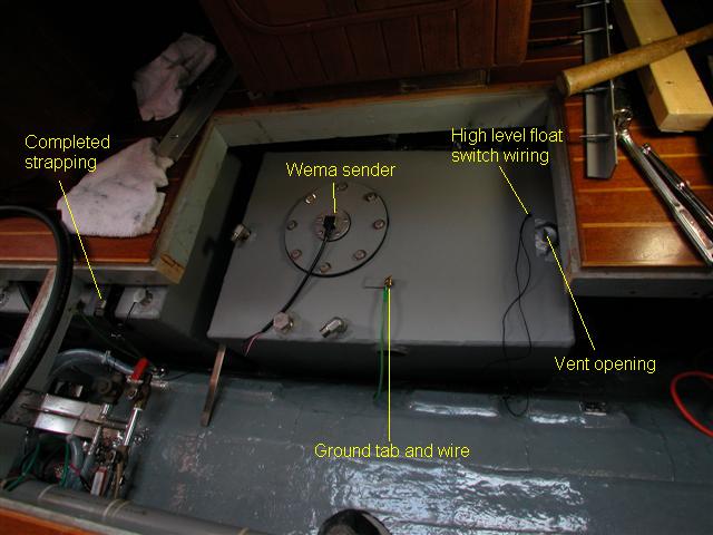
Number 1 tank drops in, slides forward
Tank number one dropped in and slid into place. The mounting bars were then slid under the tank. This is the only way the level sender head would fit under the framimg. The hole in the front is for the tank vent, installed after the tank is in place. Before increasing the distance between tanks for floor supports, the pickup at the back of this tank was in the large opening. It ended up under the floor panel in front.
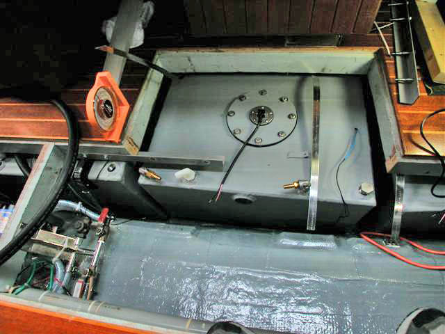
Last tank installed is number two. Note tank #1 is still pushed forward to allow number two to fit.
Floor and installation angles were measured using the dial level shown on the floor in the above photo. The stainless straps had to be attached to the inaccessible side prior to tank installation. The white plastic fitting was replaced with one of the custom 3/4" NPT elbows.
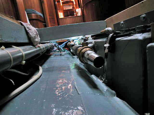
Adding the fittings and hose as the tanks are installed
The tank fills were carefully installed to ensure constant downward runs with the boat in its normal resting position. The first three tanks are successively shorter going forward, and the fill opening heights also decrease as you move forward. On our boat the original fill is aft, so tanks one through three were chained together. I installed valves inline between the three tanks to ensure fuel does not redistribute itself when we are heeled. Tank four has it's own fill, tank five is the day tank and cannot be directly filled.
The fill hoses were installed as the tanks were positioned. Most of the fittings were installed after the tanks were secured.
Back to Pre-Installation Page
Forward to Plumbing Page


