Pre-Installation Work
Tank Attachment
The standards require the tanks to be secured well enough to not move more than 1/4". They can not be used to support the floor, which would cause flexing and possibly lead to weld failure. The original installation used wedges between the tank and the floor.
The new installation uses 0.030" thick, 3/4" wide stainless steel strapping to secure the tanks to the hull. The strapping attaches around a 1/4 bolt which passes through a stainless steel bracket. The brackets are screwed into wood fiberglassed to the sides of the bilge. The paint had to be stripped from the fiberglass around the new wood supports. The wood was glassed in place with matting, corners filled in with resin gel, and glassed over with roving. The bilge was painted with gray bilge paint.
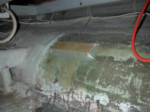
Fiberglassed wood support - note the paint removal under the new fiberglass
The bracket end of the strapping terminates in a loop fabricated by doubling the strapping back on itself and spot welding. Once two pieces are bolted to the brackets they are joined using Band-It stainless steel banding buckles. The breaking strength of the banding and buckles is well over 2000 lbs - maximum full tank weight is 250 lbs, there are two straps per tank with an expected load of 125 lbs each.
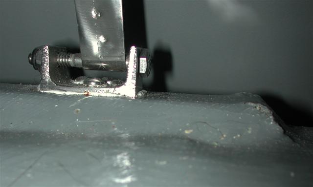
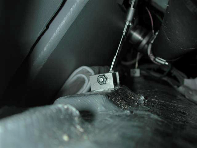
The bolt through the stainless channel was angled to match the bilge angle.
Chain Locker Drain Pipe
The old chain locker drain pipe ran down the middle of the bottom of the boat to the mast area, then ran outside the old tank mounts under the tanks. Since I didn't want to lose that much vertical distance, especially up forward where space was tight, I re-ran the chain locker drain pipe along the sides of the bilge. I decided to let the mast step area drain under the new tanks, however I didn't want potentially muddy and odiferous chain locker drain smelling up the interior of the boat.
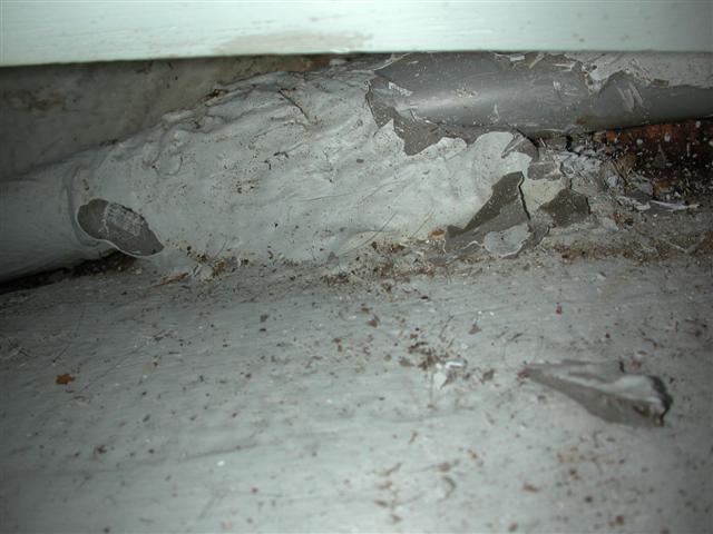
Under the forward cabin sole, the original pipe was held in place by a blob of resin
I removed the resin attaching the pipe to the bilge under the forward cabin floor and cut the old PVC pipe where it exited the forward berth. I glued a new piece of PVC pipe in and routed it along the side of the bilge instead of the old route, straight down to the mast step. The PVC pipe was attached to wood epoxied to the bilge. It runs from the forward cabin down to the turn of the bilge, then aft through the bulkhead forward of the engine. The pipe drains into the bilge under the engine.
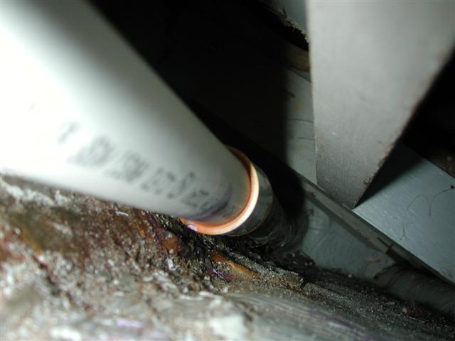
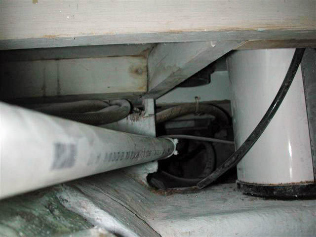
It wasn't difficult ensuring a steady downhill run for the drain pipe
Water system
The water manifold was in the way of the new fuel fill and the water pump mount was removed during the tank removal process. I wanted a new pump mount to accomodate both the old water pump and the new fuel pump. The new mount incorporates proper isolation mounts to decrease the noise from the pumps.
Additionally, all water hose under the floorboards was replaced. All water connections were moved to accessible places. Supports for hoses on the port side of the tanks were fabricated from PVC pipe coupling to create 'hangers' supporting the hose loosly enough to allow replacement.
Back to New Tanks Page
Forward to Installation Page


